why
We all know that roots are the organ system that gives plants some structure and allows them to access nutrients and water, affecting the hydrological cycle. Since the distribution of these resources is non-uniform in the soil, the position, shape, and density of plants’ roots influences their uptake efficiency. Less popularly, roots also produce metabolites that help make soil the planet’s store of carbon by excellence.
Isn’t it fascinating that despite lacking a centralized information processing center (like our nervous system), plants joggle responses to several complex environmental inputs? How could we use this knowledge to help them make a more efficient use of their resources with a sustainable agriculture vision in mind?
When it comes to optimizing, let alone designing, these roots, we’ve been limited by our ability to design and build predictable genetic systems in plants, especially when no native promoters are available. Unlike other organisms, plants have proven to need longer timelines and it’s been hard to tune circuit activity across heterogenous plant cells.
This study thus develops quantitative transient expression assays as a platform to test and tune genetic circuits in plants.
what
As a refresher, transcription factors (TFs) are molecules that help in the process of gene expression in humans and other eukaryotes like plants. General TFs aid in the overall binding of RNA polymerase to DNA while specific ones aid the former ones in the binding to specific promoters.
When thinking of genetic logic you can imagine a specific combination of transcriptional regulators (a.k.a, TF) needed to unlock, or lock, the expression of genes. Synthetic biology comes in when we want to intelligently design and express the logic we want in living things or its parts.
This paper specifically, builds synthetic transcriptional regulators that can be compiled to create genetic circuits that perform Boolean logic:
transcriptional activators: bacterial DNA-binding proteins + 6x VP16 activation domains (operators) + SV40 NLSs.
9/10 turned on their target promoters
7 were specific to their target
transcriptional repressors: @ the end of CaMV 35S promoter (strong constituitive promoter in plants)
4/10 had a >2x change in gene expression
notes: mCherry was used to normalize the fluorescence measurements (as a point of reference). Promoters were also engineered to tune expression levels by changing the # of transcription factors binding sites (operators) in the AmtR promoter and ≥3 was the ideal number. Location of the operator also affected repression and dynamic range.
The actual logic gates and genetic circuits were built in the following way:
input: plasmid with a transcriptional regulator like an activator, a repressor, or both.
output: plasmid with recognition sites for the input(s) + specific promoter + gene of interest
This took me a while to understand. Unlike electrical engineering (I think), in biological engineering it’s the outputs that we program to create the logic that we want—they themselves are the gates.
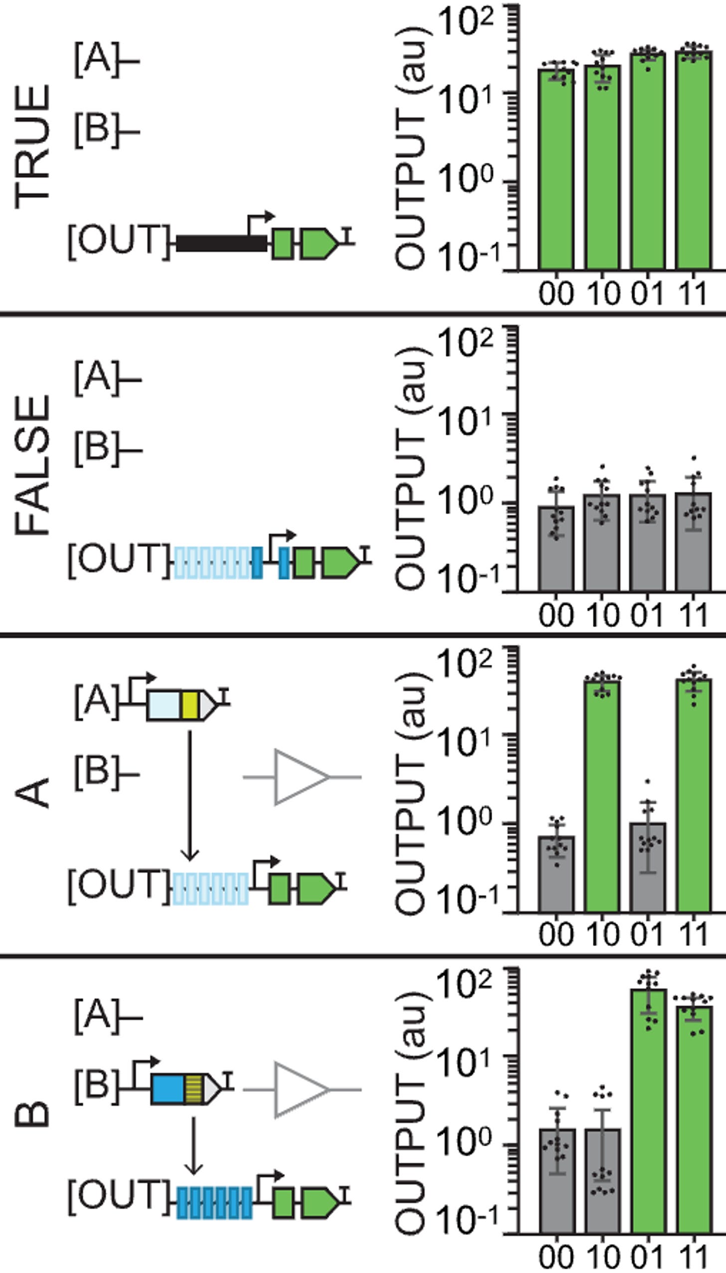
A TRUE gate works by using a constituitive promoter (no inputs needed), a FALSE gate is built with TF binding sites yet no inputs, and the buffer gates use TF binding sites for either an A or a B type of input (activator).
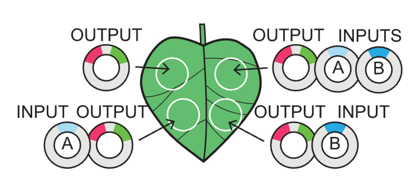
Just as the leaf above explains:
00 is an output alone
10 is a type A input
01 is a type B input
11 is both A and B inputs
Thus, something like buffer B gate would look like a leaf in which only the two right circles of the plant light up with GFP because the outputs are built such that they only recognize a type B input (01 and 11).
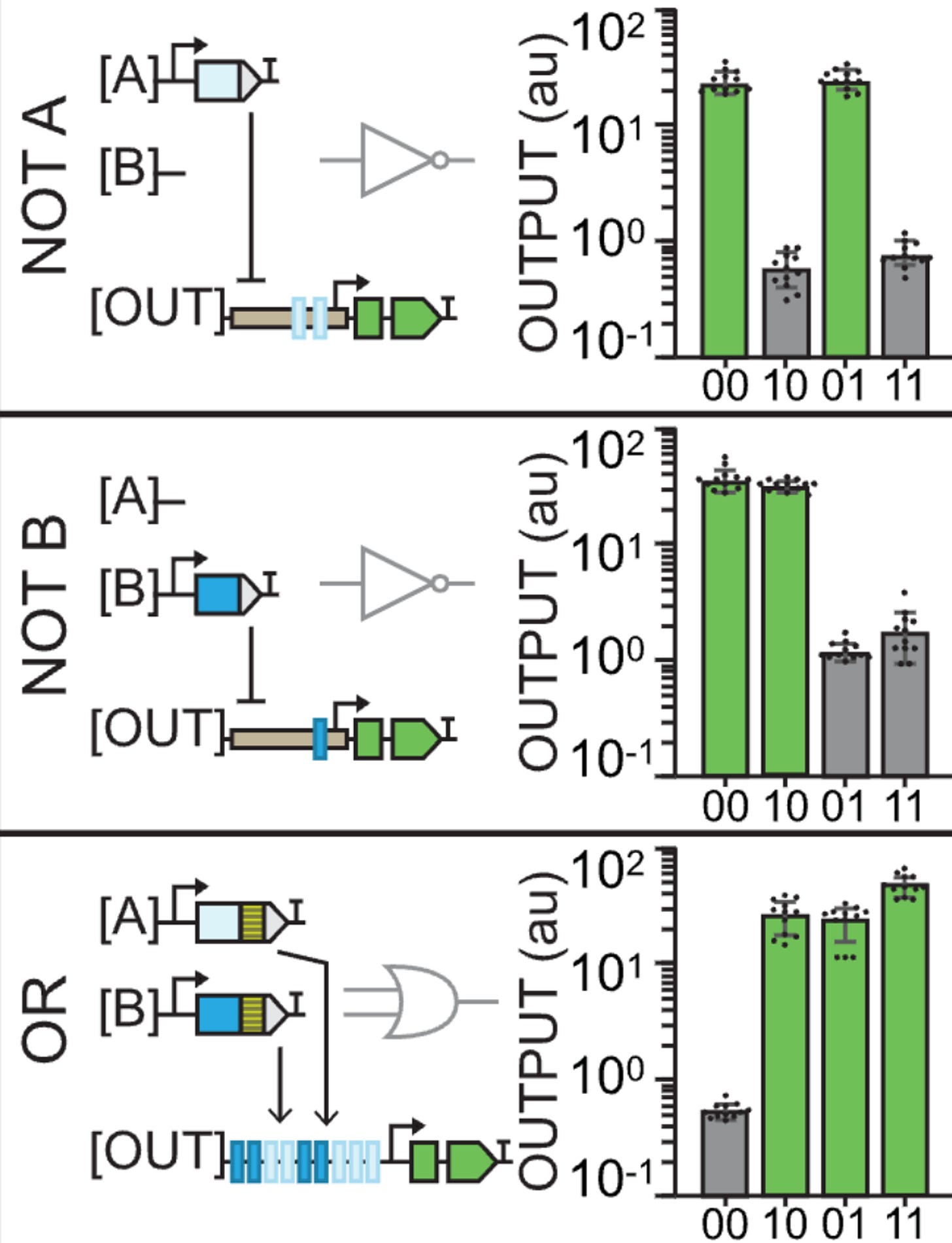
The reason why 00 does output GFP again in the NOT gates is because they’re using the pro35S constituitive promoter. The outputs that are built with type A recognition sites thus create logic gates (outputs) that show no GFP in 10 and 11 because that’s where the repressors are acting. Similar with NOT B.
An OR gate starts to get a little more interesting: having both A and B binding sites and both A and B input activators means that only the site of the leaf where you don’t apply any inputs will be off.
If you’re a bit stupid like me, the leaf diagram can either be a source of confusion or a magnificent explanatory tool. The reason why the graphs sometimes show no GFP expression is not because of an inherent quality of that output but because of the lack of an input. It’s kinda obvious once you get it. The graphs are only a way of representing what happens in each case (leaf diagram). It’s only the design of the outputs (the logic gates) that changes.
Of course that Jenn Brophy, my current CEO (Chief Engineer of Organisms), didn’t stop there. She built 14 gates in total and they only increase in complexity.
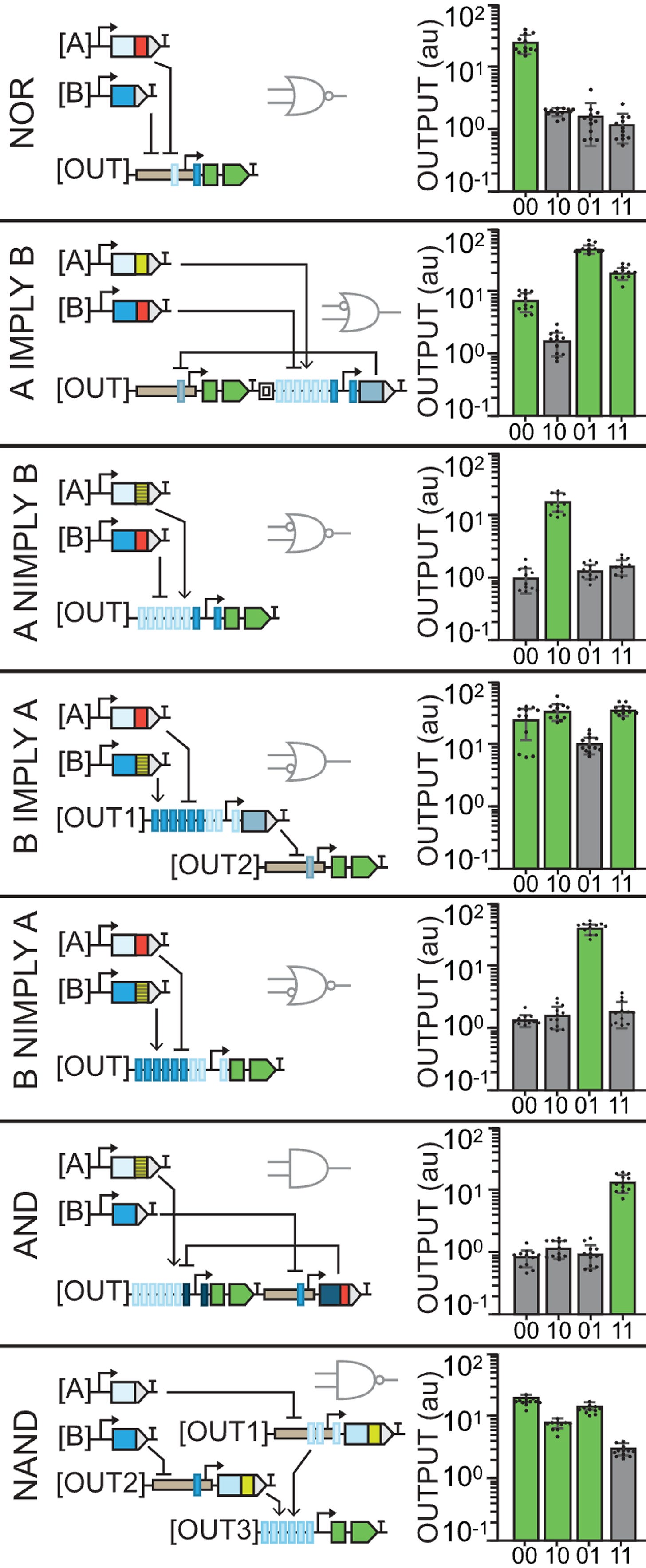
The NOR gate uses the pro35S again so we observe GFP in 00. However, the output contains recognition sites for both inputs which are repressors so expression is blocked in the rest of the cases.
A IMPLY B is the first weird gate that uses an insulator between the two parts of the output (the GFP and the repressor). In this one, the constituitive promoter will produce GFP unless A is present to activate the repressor.
A NIMPLY B is the opposite case: GFP will only be produced when A and only A is present. Otherwise, there’s no constituitive promoter for 00 and B will repress even in the presence of A.
You may notice that what are usually among the simplest gates, AND and NAND, are the last and apparently most complex ones here. Instead of using insulators, our CEO used 3 different plasmids for the outputs in NAND.
At this point, I think we get it: const. promoter with no inputs gives us GFP, having one of the repressors can reduce expression and having both decreases it even more but not completely, in this case. Pretty cool.
So what
Pretty cool, except we’re not done yet. If you’re a bit curious like me, you may be asking what in the world we want these things for. Well, if we use tissue-specific promoters, for example, we will be able to induce expression of a gene of our interest, only in a specific regions as such:
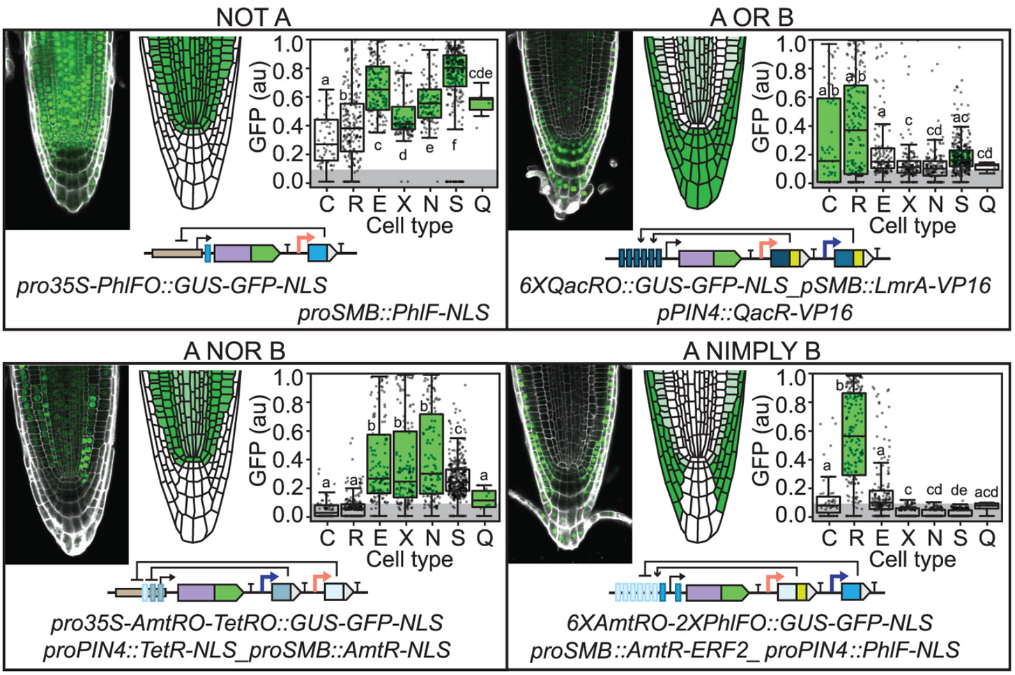
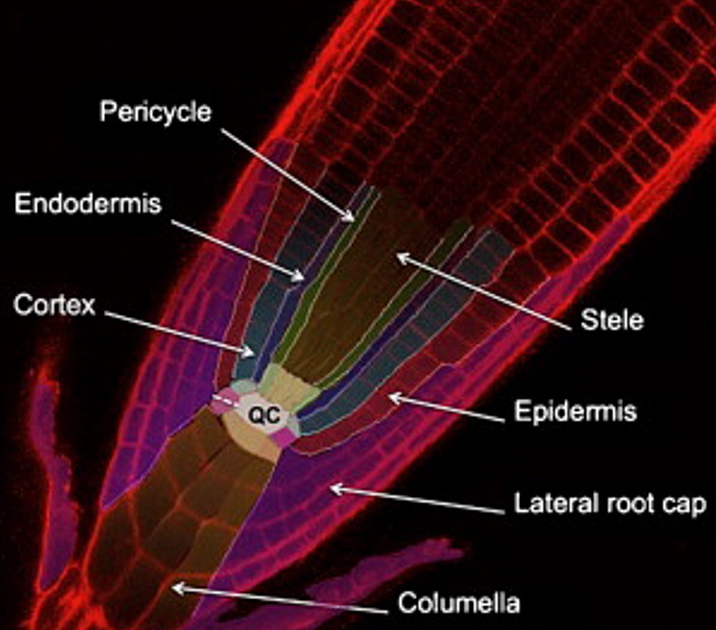
This last gates figure presents the same idea, the same gates. The inputs and outputs are simply “linearized” and the instead of having A and B we now have orange and purple which represent the promoters SOMBRERO (SMB) which is expressed in the entire root cap and PIN-FORMED 4 (PIN4), expressed in columella, root cap, and stele). For reference, check out →
A challenge in shaping roots has been that some genes involved affect different the process in different ways. For example, increasing expression of solitary root (slr-1) eliminates root branching but also hinders root gravitropism, root hair development, and primary root growth. To prevent the unintended effects, the authors use proGATA2323, a tissue-specific promoter called proGATA2323 that restricts the impact of slr-1 to lateral roots (no unintended effects).
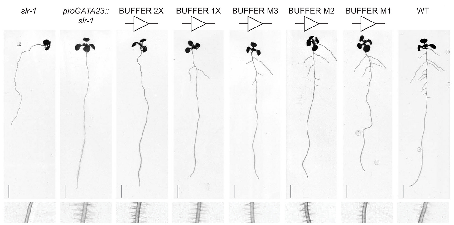
This last figure shows quantitative expression of slr-1, depending on the number of activator domains of the promoter and the mutations made to its key residues to further tune expression. The gates work exactly as was previously explained.
All in all, genetic circuits in plants give us to control root growth for more efficient water and nutrient uptake. Future innovations in this space will allow us to further see plants as platforms, to utilize their fantastic biomanufacturing capabilities, both above and below the ground, in-vitro and in-planta, to produce useful compounds in response to highly specific inputs.


